قد يؤدي سوء تخطيط المناطق، وتفاوت درجات الحرارة، وعدم كفاءة توزيع المياه إلى ارتفاع تكاليف الطاقة وتقليل العمر الافتراضي للنظام. وتوفر المشعبات والمشغلات المطابقة بشكل صحيح تحكماً دقيقاً وموثوقاً.
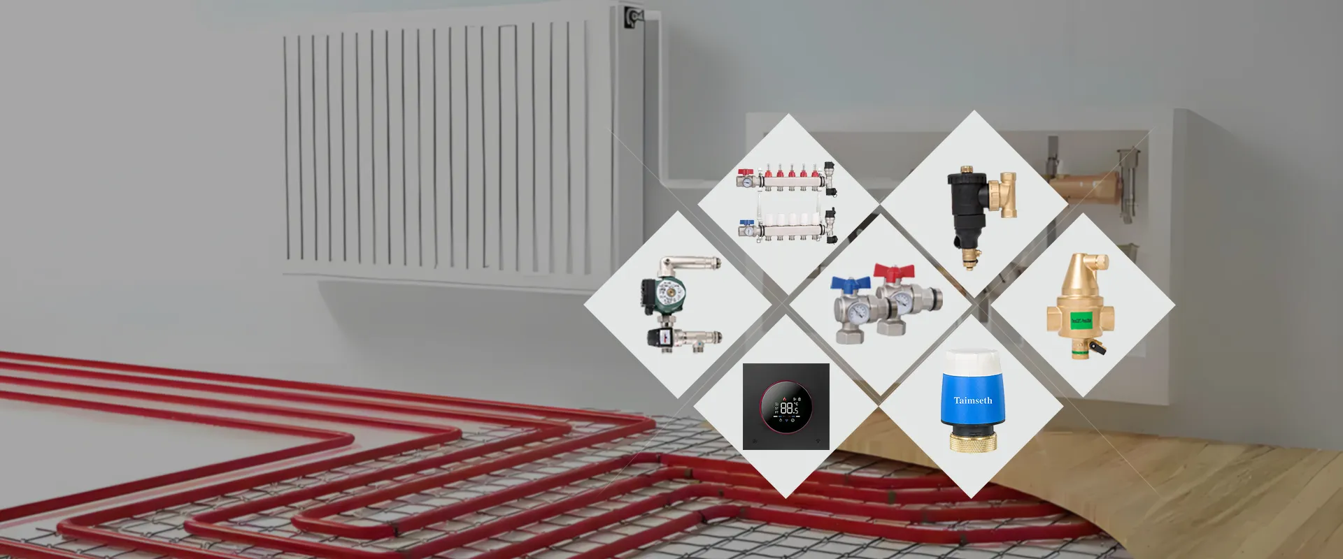
يقوم مشعب التدفئة الأرضية المائية بتوزيع الماء الساخن على دوائر الأنابيب الفردية، بينما تتحكم المشغلات الحرارية في كل دائرة وفقًا لإشارات منظم الحرارة في الغرفة. وتعمل هذه المكونات مجتمعةً على دعم تقسيم المناطق، والموازنة الهيدروليكية، واستقرار درجات الحرارة الداخلية، وتشغيل النظام بكفاءة. ويُعد تحديد الحجم الصحيح، والتوافق الكهربائي، والتشغيل الاحترافي أمورًا أساسية لضمان الأداء الموثوق به على المدى الطويل.
تشرح الأقسام التالية وظائف المكونات، ومعايير الاختيار، وأولويات التركيب، والاعتبارات المتعلقة بالتكامل في مشاريع التدفئة المائية الاحترافية.
ما هو مشعب التدفئة المائية تحت الأرضية؟
يُعد مشعب التدفئة الأرضية المائية نقطة التوزيع الرئيسية لنظام التدفئة. حيث يستقبل الماء الساخن من غلاية أو مضخة حرارية أو أي مصدر حراري آخر، ثم يوزع الماء إلى دوائر منفصلة للتدفئة الأرضية.
عادةً ما يخدم كل دائرة غرفةً أو منطقةً أو مساحةً معينةً في الطابق. ويتيح هذا الترتيب لنظام التدفئة التحكم في كل منطقة على حدة بشكل مستقل، بدلاً من التعامل مع المبنى بأكمله كمنطقة واحدة غير خاضعة للتحكم.
قد تشتمل مجموعة المشعب النموذجية على ما يلي:
- رؤوس الإمداد والعودة
- مقاييس التدفق
- صمامات الموازنة
- صمامات العزل
- فتحات تهوية أوتوماتيكية أو يدوية
- نقاط التعبئة والتصريف
- مقاييس درجة الحرارة أو الضغط
- وصلات تثبيت المشغّل
اعتمادًا على تصميم النظام، قد تشتمل المجموعة أيضًا على مضخة تدوير، أو صمام خلط، أو صمام تجاوز، أو وحدة التحكم في درجة الحرارة، أو خزانة التوزيع.
تُصنع مشعبات المياه عادةً من الفولاذ المقاوم للصدأ أو النحاس أو المواد المركبة الهندسية. ويجب أن تتحمل المادة المختارة الدوران المستمر للمياه وضغط التشغيل والتغيرات في درجات الحرارة والاستخدام على المدى الطويل.
لماذا يُعد التوازن الهيدروليكي أمرًا مهمًا؟
يتدفق الماء بطبيعة الحال عبر المسار الذي يتميز بأقل مقاومة هيدروليكية. وفي نظام التدفئة الأرضية غير المتوازن، قد تتلقى الدوائر الأقصر تدفقًا مفرطًا من الماء، بينما تتلقى الدوائر الأطول تدفقًا غير كافٍ.
قد تؤدي هذه الحالة إلى:
- الغرف شديدة الحرارة
- المناطق ذات الأرضيات الباردة
- تقلبات درجات الحرارة داخل المباني
- التشغيل المفرط للمضخة
- زيادة استهلاك الطاقة
- تقلبات درجات حرارة مياه العودة
تتيح أجهزة قياس التدفق لمهندسي التشغيل ضبط كل دائرة وفقًا لطول الأنابيب فيها، وحمل التسخين المحسوب، وفقدان الضغط.
يضمن التوازن الصحيح حصول كل منطقة على الكمية المطلوبة من الماء الساخن دون إجبار مضخة الدوران على العمل بسرعة عالية دون داعٍ.
قبل بدء عملية الموازنة، يجب ملء الأنابيب بالكامل، وشطفها، واختبار ضغطها، وتفريغ الهواء منها. فقد يؤدي الهواء المحبوس داخل الدائرة إلى تقييد الدورة الدموية وجعل قراءات مقياس التدفق غير دقيقة.
بعد بدء التشغيل، يجب تسجيل الإعدادات النهائية للتدفق لاستخدامها في عمليات الفحص أو الصيانة أو تعديل النظام في المستقبل.
ما هو المشغل الحراري؟
المشغل الحراري هو جهاز يتم التحكم فيه كهربائيًّا ويتم تركيبه على وصلة الصمام في المشعب، وعادةً ما يكون ذلك على أنبوب العودة.
ويتمثل الغرض الرئيسي منه في فتح أو إغلاق دائرة تدفئة فردية استجابةً لإشارة صادرة عن منظم حرارة الغرفة، أو وحدة التحكم في المنطقة، أو وحدة الأسلاك المركزية.
وتكون خطوات التشغيل عمومًا على النحو التالي:
- يكتشف منظم درجة حرارة الغرفة أن درجة الحرارة الداخلية أقل من القيمة المحددة.
- يرسل منظم الحرارة إشارة كهربائية إلى المشغل المقابل.
- يقوم المشغل بفتح صمام المشعب تدريجيًّا.
- يدور الماء الساخن عبر الدائرة المخصصة للطابق.
- يقوم منظم الحرارة بإيقاف الإشارة بعد الوصول إلى درجة الحرارة المطلوبة للغرفة.
- يقوم المشغل بإغلاق الصمام وإيقاف التدفق عبر تلك المنطقة.
تعمل المشغلات الحرارية عمومًا بهدوء وتستهلك كمية قليلة نسبيًّا من الكهرباء. كما أن حركة فتحها التدريجية يمكن أن تقلل من التغيرات المفاجئة في الضغط داخل النظام المائي.
تشمل الفولتية الشائعة لتشغيل المشغلات ما يلي: 24 فولت و 230 فولت. يجب أن يتوافق الجهد المختار مع منظمات الحرارة، ومركز التوصيلات الكهربائية، والمحول، والتصميم الكهربائي للمشروع.
مشغلات مغلقة عادةً ومفتوحة عادةً
تتوفر المشغلات الحرارية عادةً في نمطين من أنماط التشغيل.
مشغلات مغلقة عادةً
يحافظ المشغل «المغلق عادةً» على صمام المشعب مغلقًا في حالة انقطاع التيار الكهربائي. ولا يفتح الصمام إلا بعد أن يتلقى المشغل إشارة تحكم.
يُستخدم هذا التكوين على نطاق واسع لأن دائرة التدفئة تظل معطلة عند إيقاف تشغيل نظام التحكم.
مشغلات مفتوحة عادةً
يحافظ المشغل «المفتوح عادةً» على الصمام مفتوحًا في حالة انقطاع التيار الكهربائي. ولا يُغلق الصمام إلا بعد أن يتلقى المشغل إشارة كهربائية.
يمكن اختيار هذا التكوين عندما يُعتبر الحفاظ على الدوران أثناء انقطاع التيار الكهربائي أو تعطل نظام التحكم أمرًا مهمًا من الناحية التشغيلية.
يعتمد الخيار الصحيح على:
- استراتيجية التحكم
- تصميم مصدر الحرارة
- تشغيل المضخة
- متطلبات السلامة
- منطق نظام إدارة المبنى
- الاستجابة المتوقعة أثناء انقطاع التيار الكهربائي
لا ينبغي الخلط بين المشغلات المفتوحة عادةً والمغلقة عادةً دون وجود استراتيجية تحكم محددة بوضوح.
معايير اختيار المكونات الرئيسية
يجب أن تكون المشعبات، وملحقات الصمامات، والمشغلات، وأجهزة تنظيم الحرارة، ومراكز الأسلاك متوافقة من الناحية الفنية.
تشمل عوامل الاختيار المهمة ما يلي:
التوافق الميكانيكي
يجب أن يتوافق سن المشغل والمهايئ وشوط التشغيل وقوة الإغلاق مع صمام المشعب.
قد يؤدي التوصيل غير الصحيح إلى منع الصمام من الفتح أو الإغلاق بشكل كامل.
التوافق الكهربائي
يجب أن يتوافق جهد المشغل والحمل الكهربائي مع منظم الحرارة ومركز الأسلاك والمرحل والمحول.
كما يجب على المصممين التأكد من متطلبات الكابلات ومستويات الحماية الكهربائية.
عدد دوائر التدفئة
يجب أن يتوافق عدد منافذ المشعب مع عدد دوائر التدفئة الأرضية.
في الحالات التي يُمكن فيها التوسع مستقبلاً، يمكن تضمين منافذ احتياطية في المشعب خلال مرحلة التصميم الأولية.
نطاق التدفق
يجب أن تدعم عدادات التدفق في المشعب متطلبات تدفق المياه المحسوبة للدوائر الفردية.
يجب أن يتيح النطاق المختار إمكانية الضبط الدقيق، بدلاً من إجبار عدادات التدفق على العمل عند حدودها الدنيا أو القصوى.
تكامل أنظمة التحكم
قد تتطلب المشاريع المرتبطة بنظام إدارة المباني واجهات ترحيل، أو وحدات تحكم، أو أجهزة مراقبة عن بُعد، أو بوابات اتصال.
تكتسي الوثائق الفنية الواضحة أهمية خاصة في المشاريع الدولية، لأن المعايير الكهربائية وممارسات التركيب ومتطلبات التحكم قد تختلف من منطقة إلى أخرى.
متطلبات التثبيت
يجب تركيب المشعب في مكان يسهل الوصول إليه ويكون مركزياً إلى حد معقول.
يمكن أن يؤدي الموقع المركزي إلى تقليل أطوال الدوائر، وتبسيط عملية الموازنة، وتحسين إمكانية الوصول لأغراض الصيانة.
كما يجب أن يكون المشعب:
- مستوى التركيب
- مدعوم بأمان
- محفوظ داخل خزانة مناسبة
- يمكن ضبط التدفق
- يمكن الوصول إليه لاستبدال المشغل
- تم تركيبها مع ترك مسافة كافية للأسلاك
قبل التشغيل، يجب شطف كل دائرة وتعبئتها وتهويتها واختبار ضغطها.
يجب على المُركِّبين التحقق مما يلي:
- مهام منظم الحرارة
- توصيلات المشغل
- تشغيل الصمام
- أجهزة قفل المضخات
- إشارات مصدر الحرارة
- درجة حرارة مياه الإمداد
- معدلات تدفق الدائرة
أثناء التشغيل التجريبي، يجب اختبار كل منطقة على حدة. يجب أن يفتح المشغل الصحيح عندما يطلب منظم الحرارة المقابل توفير التدفئة.
كما يجب على المهندس التأكد من أن الماء يدور عبر الدائرة المقصودة، وأنه لم يتم تخصيص أي صمامات أو مشغلات أو وصلات ترموستات بشكل خاطئ.
التكامل مع نظام التدفئة والتهوية وتكييف الهواء (HVAC) الكامل
لا يمكن اختيار الموزعات والمشغلات بشكل منفصل عن التصميم العام لنظام التدفئة.
يتأثر أداؤهم بما يلي:
- فقدان الحرارة في المباني
- بناء الأرضيات
- المسافة بين الأنابيب
- طول الدائرة
- درجة حرارة الماء
- ضغط المضخة
- أداء العزل
- قدرة مصدر الحرارة
- إعدادات التحكم
بالنسبة للمشاريع التجارية أو الصناعية الكبيرة، يمكن تنسيق تشغيل المشعبات مع مضخات الدوران ومحطات الخلط والمضخات الحرارية والغلايات وأنظمة إدارة المباني ومنصات مراقبة الطاقة عن بُعد.
تقدم شركة «جيني» لحلول التدفئة والتهوية وتكييف الهواء (HVAC) حلولاً صناعية وتجارية في هذا المجال، مدعومة بتصميم الأنظمة واختيار المعدات وتخطيط أنظمة التحكم وتوجيهات التركيب والتشغيل والمساعدة بعد البيع. كما قد تتضمن الحلول المخصصة أنظمة تحكم موفرة للطاقة، وتكامل مع أنظمة إدارة المباني (BMS)، والمراقبة عن بُعد وفقًا لمتطلبات المشروع.
يساعد التصميم المنسق للنظام على تحسين استقرار درجة الحرارة، والرؤية التشغيلية، وإدارة الطاقة، وكفاءة الصيانة على المدى الطويل.
الخاتمة
تساهم الموزعات والمشغلات المختارة بعناية في تحسين مستوى الراحة والكفاءة ودقة تقسيم المناطق والموثوقية على المدى الطويل في أنظمة التدفئة المائية تحت الأرضية.